A new idea to
obtain clean fusion energy
Home Introduction Calculations Videos Facebook Contact Sitemap
11.3 Confinement of positive ions and electrons with a static electric and magnetic field
More calculations etc. of the 11e idea
|
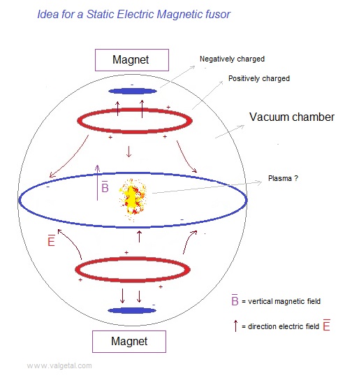
We will program the charged rings and the elipsoid of figure 1 . The rings will be aproximated/represented by an amount of point charges positioned in a circle. The negatively charged elipsoid will be aproximated/represented by a sphere, which electric field is represented by a point charge. In reality the rings and the sphere will be conductors (if we choose as material, for example, metal) and the charge on them will regroup themselves under influence of the electric field, in order to make the electric field inside the conductor zero. However, because of the given distribution of negative, positive, negative, positive and negative charge, I intuit that the regrouping of the charge in the rings and the sphere will not have a big influence on the electric field inside the vacuum chamber. Later on we could perfect the simulation. Fig. 1
To get an idea if our design is realizable in the real world,
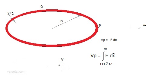
we will calculate the potentials. We give the red ring a potential V. What is then the charge Q on this ring? Fig. 2
r1= inner radius of the ring (meters); We take a point P on the outer surface of the ring, and calculate its potential Vp (due to the charge on the ring and relative to ∞). Fig.3.
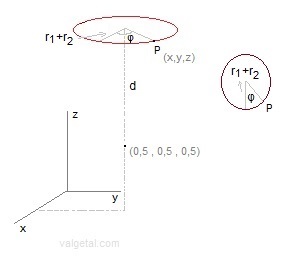
In the program we approximate (for the moment) the ring by a series of point charges situated in a circle with radius r1+r2 . The electrical potential of P = sum of the potentials caused by all the point charges dQ situated on the circle with radius r1+r2 . The Vp of a point on the outer surface (at r1+2.r2) of the ring is everywhere the same (because of symmetry). If we would calculate the Vp for other points (for example at the inner side of the ring) in this way, we would get a (slightly) different value, but we will make an approximation and consider the potential V in each point of the surface of the ring equal to Vp. (by the way, the ring is a conductor and the charge will be concentrated on the surface). In the program we introduce: the amount of point charges, r1, r2 and V. The charge of each point charge is calculated and so the electric field in the vacuum chamber. V, r1 and r2 must have realizable values. Fig.4. The positive charged ring (up and down; for the middle ring d=0).
We divide the ring in 360 point charges. Fig.5. Small negative top and bottom spheres .
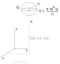
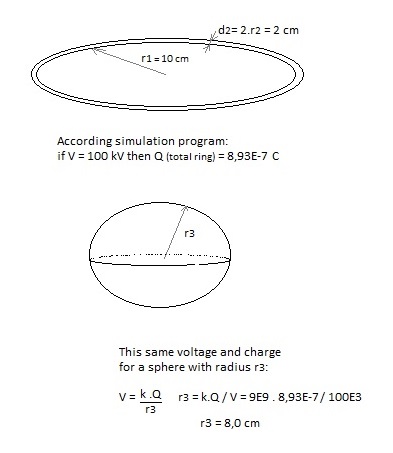
For the small negative charged top and bottom spheres we choose the radius r1, the distance d between centre simulation space and centre sphere, and the voltage V. In the program is calculated: Q = V . r1 / (9E9). This charge is supposed to be located in the centre of the sphere and so the electric field generated by this sphere is calculated. In reality the charge on the (surface) of the small sphere will move somewhat to the under side of the sphere, under influence of the other charges in the device, but I intuit that approximating the charged sphere by a point charge located in the centre of the sphere will cause only a minor error in the generated electric field. Some checking: Fig.6. Control simulation program comparing voltage and charge of the upper/down ring with a sphere.
In http://www.ifi.unicamp.br/~assis/Brazilian-Journal-Physics-V34-p1738-1744(2004).pdf , page 1741 the capacitance of a thin toroid is calculated : C = 4.π2 .ε0.a
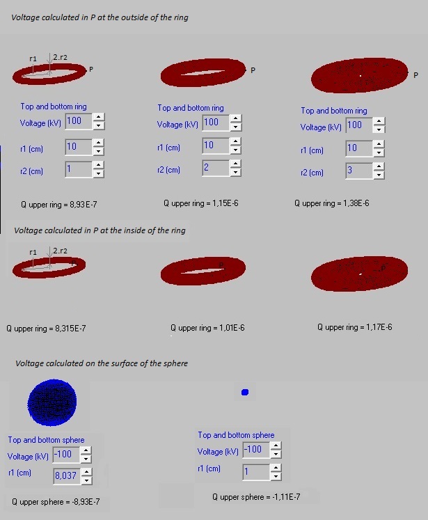
/ ( ln(8a/r0) ) with r0 << a Q = 8,93E-7 C is calculated by the program with the given voltage V, r1 and r2 More or less the same order of magnitude. The difference can be explained because not ( r2 << r1) If we take r0 = r2 = 0,0001 m, we get C = 3,9E-12 (with formula) and C = 5,2E-12 (according simulation). If we take in the simulation program point P
at the inner side of the ring, at r1, and with V=100 kV, r1=10 cm and r2=1 cm
we get Q=8,32E-7 C The point charges in the ring are distributed at r1+r2 (in the " middle"). The mean distance of P at the inner side of the ring to the point charges is a little bit less than the mean distance of P at the outer side to the point charges. So to produce the same voltage, less charge is needed. (or if the charges would be the same, the voltage would be higher at the inside). If we take in the simulation program point P
at r1+r2, in the "middle" of the ring, and with V=100 kV, r1=10 cm and
r2=1 cm we get Q=5,7E-7 C Fig. 7. 100 kV with different sizes of ring and sphere, calculating the charge.
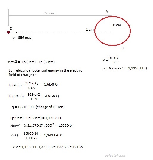
A D+ particle with a speed of 3E6 m/2 and positive charged
sphere with radius 8 cm.
If we use in our simulation program a ring with a radius of 10 cm and a
voltage of 200 kV we also stop (confine) the D+ ions
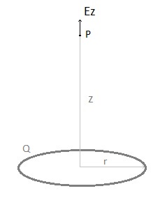
To check the program we will calculate the electric field produced by a charged ring in point P, both with a formula and with the program. fig. 9.
Ez = 9.109 .Q.z / (z2 + r2)3/2 (see: hyperphysics ) According the simulation program with V=100 kV, r2=1 cm, r1=10 cm -> Qring = 8,93E-7C -> Ez (z = 0,50 mtr) = 30,31 E3 V/m According the simulation program -> Ez (z=0,50 mtr) = 30,00 E3 V/m
|
|
|
|
