|
Applying an "magnetic
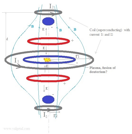
mirror" magnetic field, as illustrated in figure 1, we'll get
(probably) an
extra method to stop the particles escaping in the vertical direction.
So the positive deuterium ions and the electrons in the SEM fusor will be
confined both by the static electric field generated by the charged rings and
spheres and by the magnetic field. The magnetic field will stop them to
escape sidewards, but also (probably) helps in avoiding that they escape in the vertical
direction.
Fig. 1. SEM-fusor with magnetic mirror magnetic field.
In the simulation program we will input (and vary):
The currents I1 and I2.
The radii r1 and r2.
The distance d.
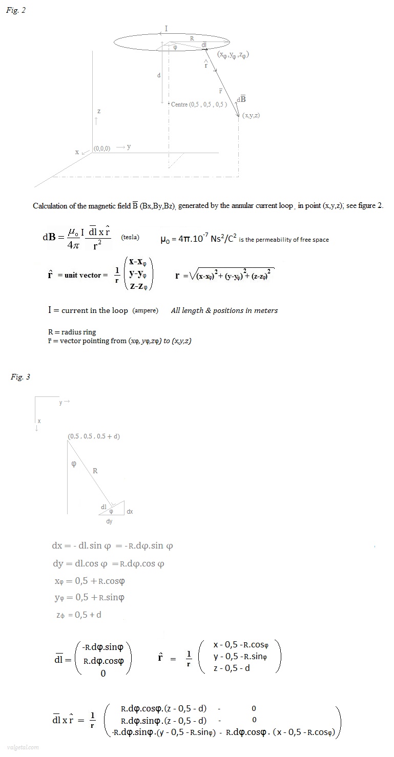
In the program we'll take a
φ=1 to 360 loop and calculate with dφ= 2π/360 -> ∑ dB in point (x,y,z).
Each dφ= 1º
.
Magnetic Confinement Concepts: a
nice animation of the magnetic mirror.
Some experiments:.
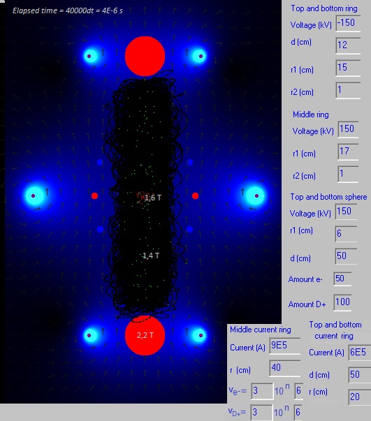
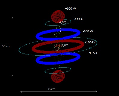
| Experiment 11.9.1. Magnetic bottle. Fig.4.
Configuration.
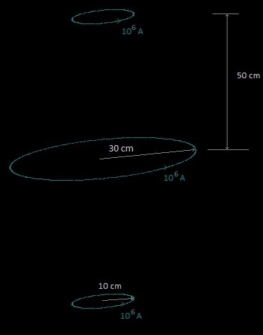
The magnetic field is produced by the three
current rings as shown in figure 4. Here only one loop is
drawn, but in reality this would be a coil consisting of many
loops/strands. The current through the coil (through one strand)
would then be less than the stated
106 A.
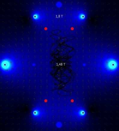
Fig. 5. The magnetic field.
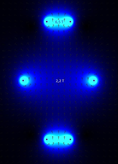
The arrows show the direction of the magnetic
field, in the plane: x=0,5 mtr (cross section through the centre of
the simulation space in a vertical plane, see fig. 2 and
coordinate system
)
. The stronger the field, the lighter the colour. In
the centre of the rings the magnetic field strength is 2,2 tesla and
6,5 tesla.
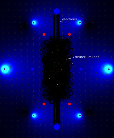
Fig. 6. Screenshot of
simulation experiment with 20 D+ ions.
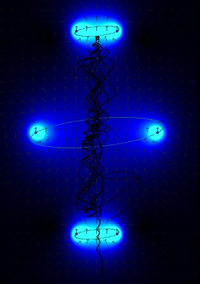
20 deuterium ions are generated in the centre region with random
speeds up to 3.105 m/s. The majority are trapped in the
"magnetic bottle"; a few ions escaped.
(dt=10-10 s).
Fig. 7. Screenshot of simulation experiment with 20 D+ ions
after some more elapsed time (2,8 10-5
s).
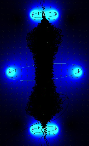
Old positions of the ions become black. 13 deuterium ions stayed
trapped; 7 ions have escaped.
Video of the experiment
Conclusion: although the applied magnetic field is quite strong
(2,2 T in the middle of the centre ring and 6,5 T in the middle of
the other rings), not all deuterium ions kept confined. The ions
were generated with random speeds up to 3E6 m/s, the same as in the
experiments with the SEM fusor. The simulation program seems to
work properly (it shows the magnetic mirror effect).
. |
| Experiment 11.9.2. Helmholtz coil
Fig. 8.
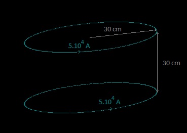
The configuration of figure 8. is called
Helmholtz coil. It produces a
region of nearly uniform magnetic field. Let's see what our
simulation program calculates..
Fig. 9. The magnetic field created by the
simulation program for the Helmholtz coil of fig. 8.
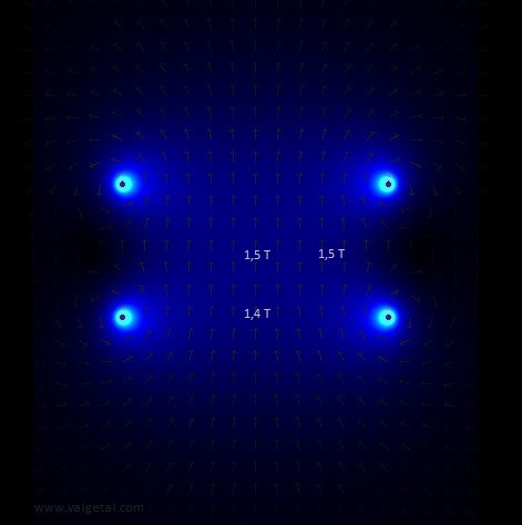
The magnetic field at the midpoint between the coils is given by
B = (4/5)3/2 . μ0.nI
/R
(see
Helmholtz_coil
)
μ0
= 4π.
10-7 T.m/A
nI = 5.105
A (total current through one coil/current ring)
R = 0,30 mtr
-> B = 1,4986 T
(the same, rounded to one decimal, as the simulation program)
Good!
. |
| Experiment 11.9.3. SEM fusor with
magnetic mirror field Similar to
Experiment 11.14a, but
with less voltages, the same initial speed of the particles
and more or less the same magnetic field strength, but now in the
form of a magnetic mirror.
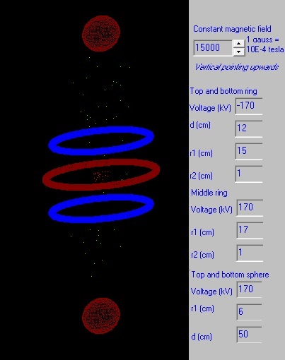
Fig. 10. The configuration of the experiment.
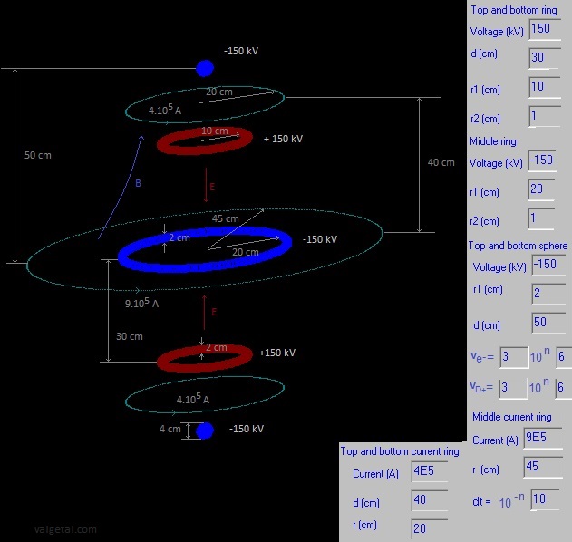 . .
Three charged rings, producing an electric field, and three
current rings producing a magnetic mirror field.
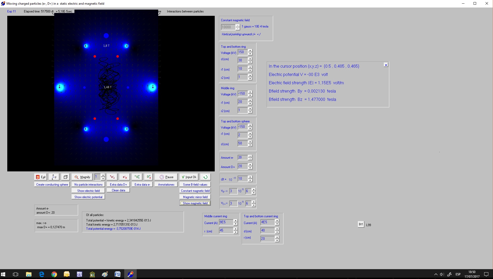
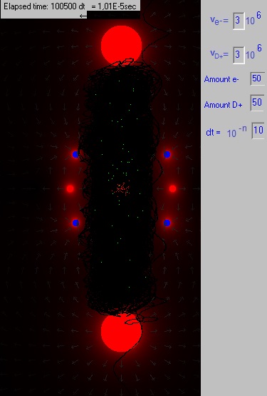
Fig. 11. Screenshot.
In the centre region 20 D+ ions have been generated with random
speeds up to 3.106 m/s.
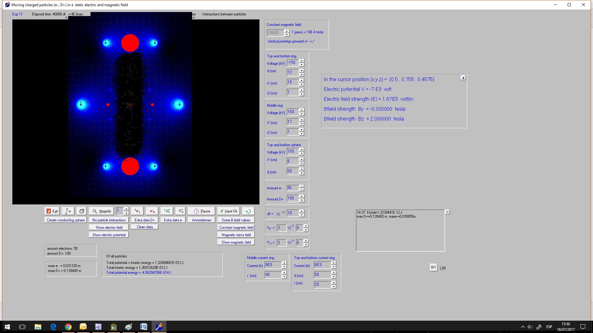
Fig. 12. Screenshot with 50 D+ ions, 20
electrons, after 5,9E-5 s.
The particles stay confined with some less
voltages (150 kV instead of 200 kV) as in the similar experiment
with a uniform magnetic field.
So applying a magnetic mirror field seems to
improve (a little bit) our SEM fusor (but it's not a panacea..).
. |
| Experiment 11.9.4. SEM fusor with
reversed polarities and with a constant magnetic field
Fig. 13.
We'll try out the configuration of fig. 13.
Fig. 14. Screenshot. The
arrows indicate the direction of the electric field; the red colour
its strength.
Two deuterium ions escaped. The applied
voltages should be a little bit higher, and the radius of the
charged rings a little bit larger.
But, as mentioned already elsewhere, the electrons stay well
confined in the centre and could form a virtual cathode, which would
attract the D+ ions and be an extra advantage for our SEM fusor.
.
|
| Experiment 11.9.5. SEM fusor with
reversed polarities and a mirror magnetic field
The dimensions are the same as in exp. 11.9.4,
the voltages a little bit less (150 kV instead of 170 kV), the
magnetic field has more or less the same strength, only it's now not
uniform but has the form of a magnetic bottle (mirror).
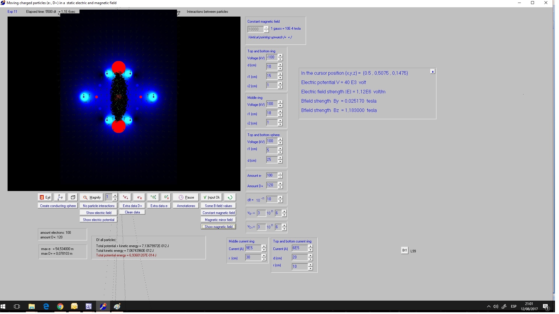
Fig. 15. Screenshot.
With this magnetic mirror field the particles stay somewhat better
confined as with the uniform magnetic field of exp. 11.9.4.
Video
of the experiment
.
|
| Experiment 11.9.6.
SEM fusor with reversed polarities, a mirror magnetic field and
reduced voltages Fig. 16.
Dimensions
Screenshot
By applying the magnetic mirror field it seems to be possible to
reduce further the applied voltages to +/- 100 kV.
But having the current loops so nearby the charges will in reality
not be very easy...
|
|
Experiment 11.9.7.
Two rings, magnetic mirror field, particles injected from below to
up Fig. 17
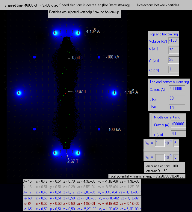
Sem Fusor with only two negatively charged rings and a magnetic
field in the form of a bottle, generated by three curring carrying
loops. The D+ ions are injected just under the bottom ring, and the
electrons just above the bottom ring. In a few points the strenght
of the magnetic field is indicated.
The total potential + kinetic energy stays constant in 3
decimals, which is an indication that the simulation program is
rather correct.
The speeds of the electrons is decreased in the program, to
simulate Bremsstrahlung:
if (vx>1E1) and (vy>1E1) and (vz>1E1)
then
Begin
vx:=vx*0.90; vy:=vy*0.90; vz:=vz*0.90;
end;
The D+ ions are a little squezed in the centre region, which is a
little advantage.
|
Back to the main page
 28 January
2018
by
Rinze
Joustra
www.valgetal.com 28 January
2018
by
Rinze
Joustra
www.valgetal.com

|